
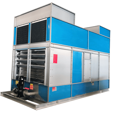
Cross Flow Closed Circuit Cooling Tower
Engineered for maximum efficiency, stability, and precise temperature control. The cross-flow design ensures easy maintenance, lower energy consumption, and reliable operation for demanding industrial and HVAC applications.
Working Principle
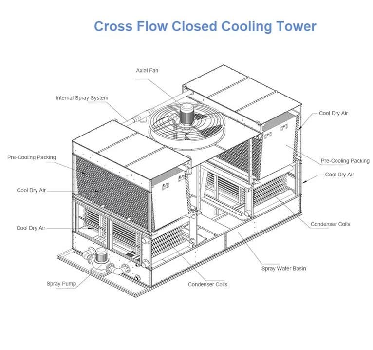
In a cross-flow closed circuit cooling tower, the process fluid flows through the heat exchange coil, completely isolated from the outside air. Spray water falls downwards over the coil and PVC fill media, while air is drawn horizontally across the falling water.
-
1
Primary Heat Transfer
The internal fluid transfers heat to the tube wall, which is then conducted to the external spray water falling over the coil.
-
2
Evaporative Cooling
The spray water absorbs heat and partially evaporates as air passes through horizontally, significantly enhancing cooling efficiency.
-
3
Clean System Operation
The closed-loop design prevents contamination, scaling, and system blockages, ensuring long-term reliability for your core equipment.
Core Components
Manufactured with premium materials for maximum durability and thermal performance in harsh industrial environments.
High-Efficiency Coils
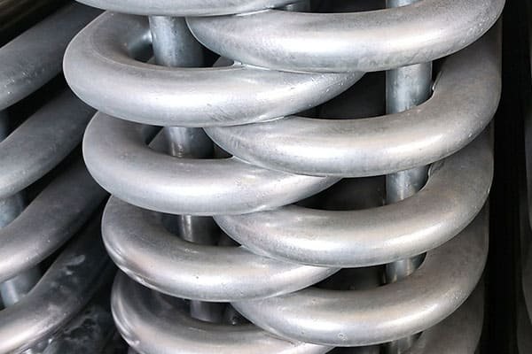
Available in 304/316L stainless steel, copper, or hot-dip galvanized steel. Tested under 2.5MPa pressure to ensure zero leaks.
Direct-Drive Axial Fan
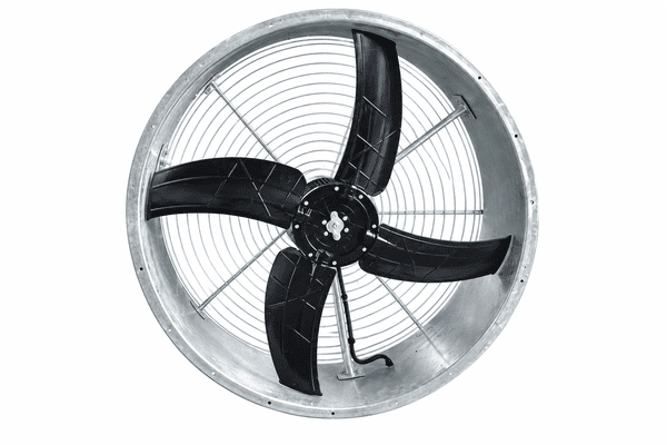
Aerodynamic aluminum alloy blades driven by a high-efficiency motor (IP55, F class) for high volume and low noise operation.
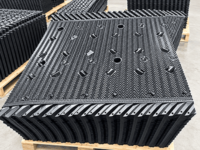
PVC Fill Media
Flame-retardant, UV-resistant PVC fill designed to maximize air-water contact area and extend retention time for better cooling.
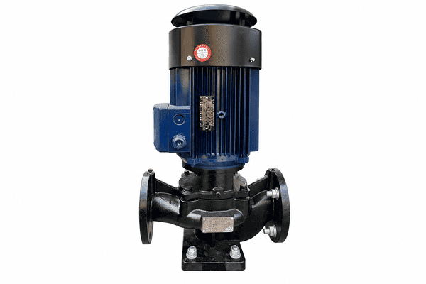
Spray Water Pump
High-flow, low-head centrifugal pump with mechanical seal. Ensures even water distribution across the coils without clogging.
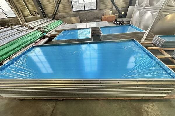
Heavy-Duty Casing
Constructed with Z275 galvanized steel or stainless steel panels, offering exceptional corrosion resistance and structural integrity.
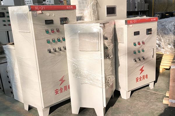
Intelligent Control
PLC-based control panel for automatic temperature regulation, variable frequency drive (VFD) options, and system protection.
Technical Specifications
Standard design conditions: Wet-bulb 28°C, Inlet 37°C, Outlet 32°C. Custom capacities and dimensions are available upon request based on your specific requirements.
| Model | Cooling Capacity (kW) | Flow Rate (m³/h) | Fan Power (kW) | Pump Power (kW) | Dimensions (L×W×H mm) | Weight (kg) |
|---|---|---|---|---|---|---|
| HFC-50 | 290 | 50 | 2.2 | 1.5 | 2400 × 1600 × 2800 | 2,850 |
| HFC-100 | 580 | 100 | 4.0 | 2.2 | 3200 × 2100 × 3100 | 4,500 |
| HFC-200 | 1160 | 200 | 7.5 | 4.0 | 4800 × 2400 × 3500 | 7,800 |
| HFC-300 | 1740 | 300 | 11.0 | 5.5 | 5600 × 2800 × 3800 | 11,200 |
| HFC-500 | 2900 | 500 | 15.0 | 7.5 | 6800 × 3200 × 4200 | 16,500 |
Data presented is for reference only. We provide precise equipment selection based on your exact working conditions. Please submit your parameters below for a customized engineering solution.
Industry Applications
Delivering reliable heat rejection for critical processes across various demanding sectors.
Data Centers
Free cooling & HVAC systems
Power & Energy
Generator & compressor cooling
Chemical Plants
Process fluid thermal control
Metal Processing
Furnace & induction cooling
Shipping & Packaging
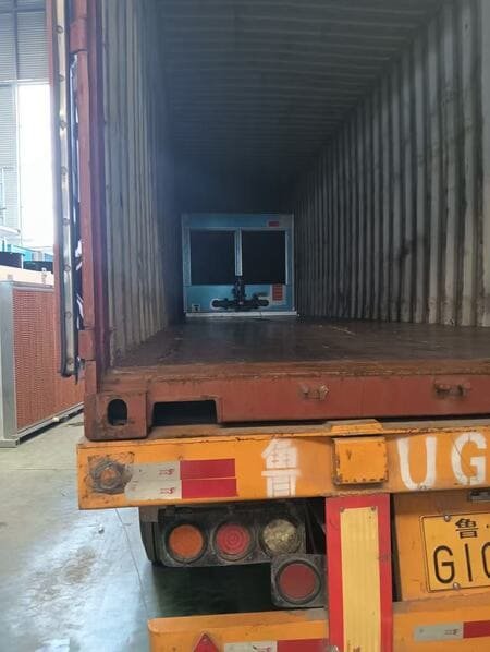
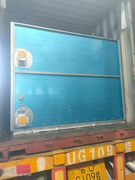
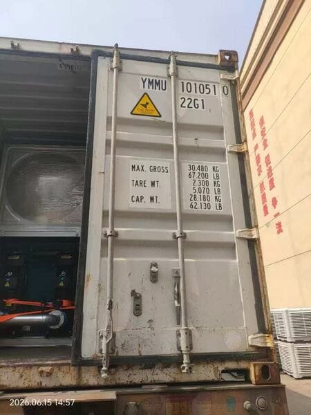
Modular design allows for safe, secure, and efficient containerized global shipping to your project site.
Get Equipment Selection
Submit your operating conditions and receive a professional cooling solution. Our technical engineers will provide accurate thermal calculations, equipment selection, and pricing within 24 hours.
Email Us
ling@hfcooling.cn
Call Us
+86 15653643728